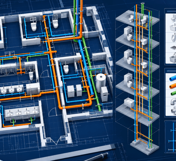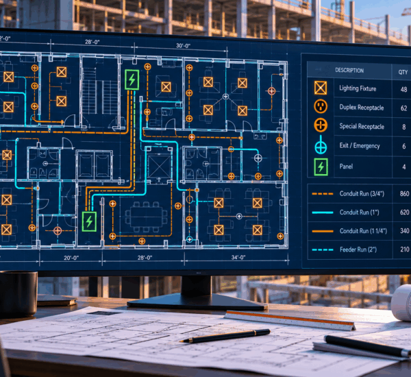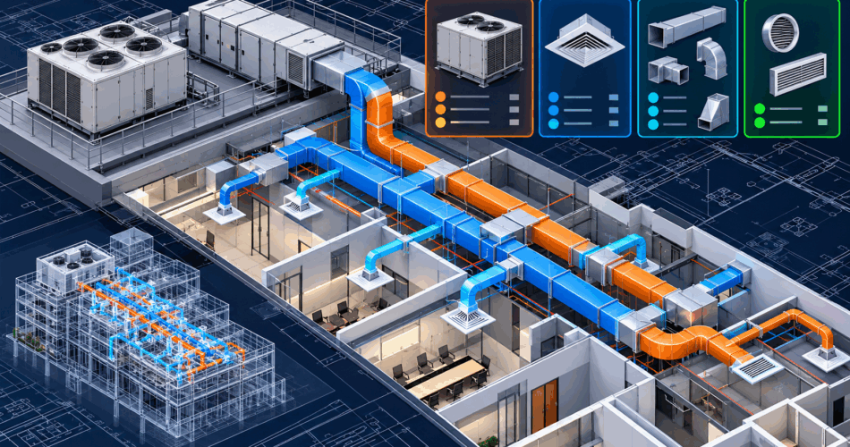
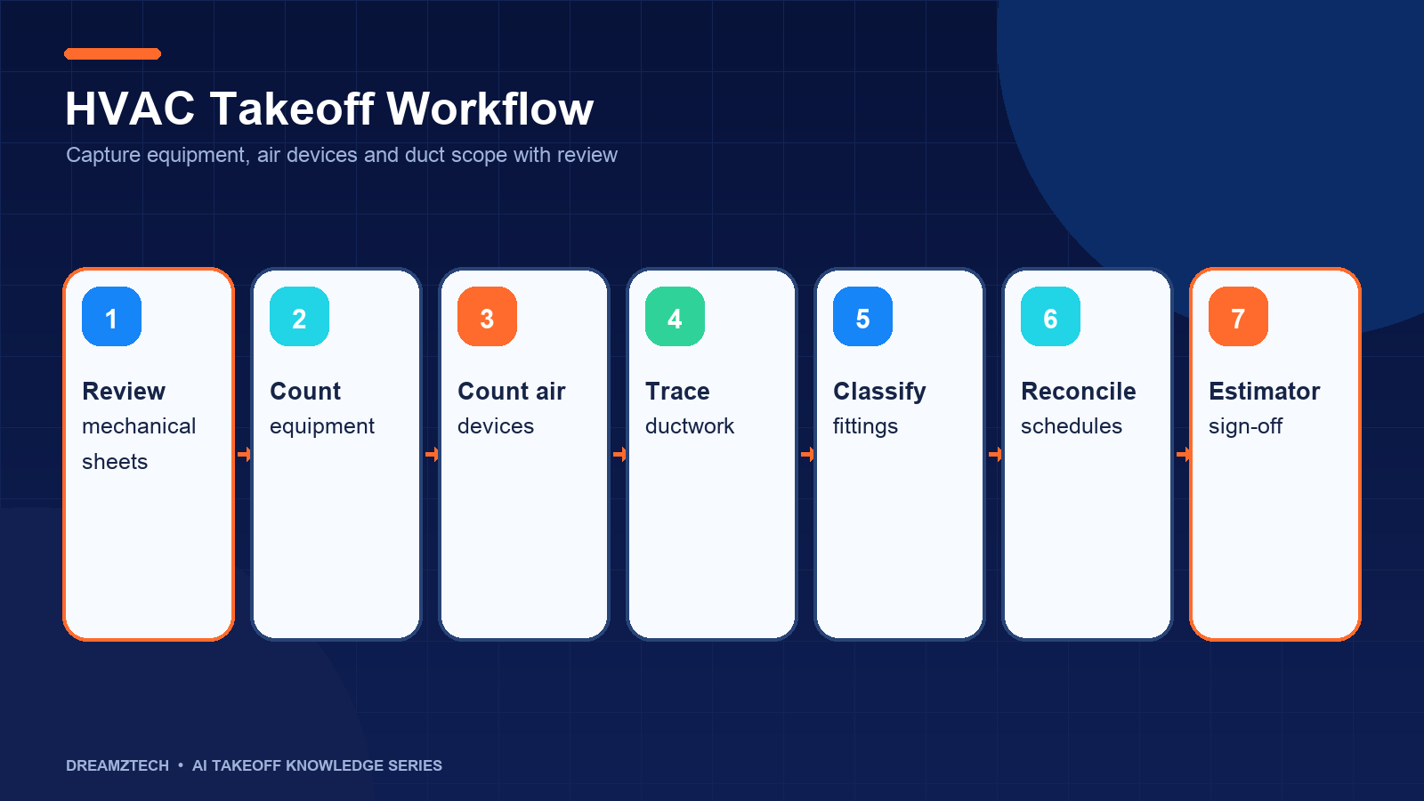
An HVAC takeoff should count equipment and air devices by schedule type, measure ductwork by system, shape and size, identify fittings and transitions, reconcile plans with equipment schedules and details, document insulation and support rules, process revisions and route quantities through estimator approval.
Mechanical takeoff is not only a tracing exercise. A duct line changes commercial meaning when its size, material, pressure class, insulation or system changes. Equipment schedules and specifications often carry scope that is not visible in the plan. Renovation sheets may combine demolition, existing-to-remain and new work.
This checklist supports manual, digital and AI-assisted workflows. DreamzTech’s HVAC takeoff software provides reviewable equipment detection, air-device counts, scale-calibrated duct measurements, schedule reconciliation and estimator-approved output.
HVAC takeoff preparation checklist
Confirm the document set
- Record drawing issue, revision and addenda
- Compare sheets with the drawing index
- Separate superseded sheets
- Identify duct plans, piping plans, schedules, details and control diagrams
- Separate new, demolition and existing work
- Flag enlarged plans and match lines
- Review mechanical specifications and addendum narratives
Confirm scope systems
- Supply air
- Return air
- Exhaust air
- Outside air
- Relief air
- Ductwork specialties
- Air devices
- Packaged and central equipment
- Hydronic piping
- Refrigerant piping
- Condensate
- Insulation and liner
- Controls
- Testing, adjusting and balancing
- Supports and seismic requirements
Confirm commercial boundaries
- Equipment furnished by owner or others
- Controls responsibility
- Electrical connections
- Roofing and curbs
- Structural supports
- Fire and smoke dampers
- Testing and commissioning
- Demolition and disposal
- Temporary systems
- Alternates and allowances
The estimator should establish these boundaries before quantities are treated as bid-ready.
Step 1: Read the notes, legends and specifications
Review mechanical notes for material, pressure, insulation, sealing, testing and installation requirements.
Map symbols and abbreviations for:
- Air-handling units
- Rooftop units
- VAV and terminal boxes
- Fans
- Diffusers, grilles and registers
- Dampers
- Louvers
- Duct systems
- Hydronic equipment
- Pumps
- Valves
- Existing and demolition work
Specifications may change what the same graphical duct run represents. Preserve links between takeoff categories and governing specification sections.
Step 2: Build the equipment and air-device classes
Equipment
- Air-handling units
- Rooftop units
- Make-up air units
- Fan-coil units
- VAV boxes
- Exhaust and supply fans
- Heat pumps
- Chillers and boilers where in scope
- Pumps
- Energy-recovery equipment
Air devices
- Supply diffusers
- Return grilles
- Exhaust grilles
- Registers
- Linear diffusers
- Louvers
- Specialty devices
Duct accessories
- Volume dampers
- Fire dampers
- Smoke dampers
- Combination dampers
- Access doors
- Flexible connections
- Sound attenuators
- Turning vanes
Organize each class according to the schedule and estimating assemblies. Equipment symbols that look similar may carry very different capacities and accessories.
Step 3: Count equipment and reconcile schedules
Count equipment by tag, not visual shape alone. For each item, capture:
- Tag
- Type
- Quantity
- Location
- Capacity or size
- Connection sizes
- Accessories
- New or existing status
- Schedule reference
Compare plan symbols with schedules and details. Investigate:
- Scheduled equipment not located on plans
- Plan equipment lacking a schedule entry
- Tag changes across revisions
- Equipment shown on roof or enlarged plans
- Duplicate symbols at match lines
- Existing equipment that should not be purchased
The schedule defines equipment characteristics; the plan provides location and context. Both are required.
Step 4: Count air devices and reconcile the air-device schedule
Count supply, return and exhaust devices by schedule type. Confirm neck size, face size, mounting and accessories where relevant.
Check:
- Typical room repetition
- Ceiling-plan coordination
- Linear footage for linear devices
- Damper or plenum requirements
- Transfer-air paths
- Devices shown only in enlarged plans
- Changed types in addenda
AI-assisted detection can accelerate repeated counts, but an estimator must review class assignments and schedule discrepancies.
Step 5: Verify scale and organize duct systems
Calibrate scale using a known drawing dimension. Large floor plans, enlarged plans and details may use different scales.
Create duct categories by:
- Supply, return, exhaust, outside or relief air
- Rectangular, round, spiral or flexible duct
- Width and height or diameter
- Pressure class
- Material
- Liner or insulation requirement
- New, existing or demolition status
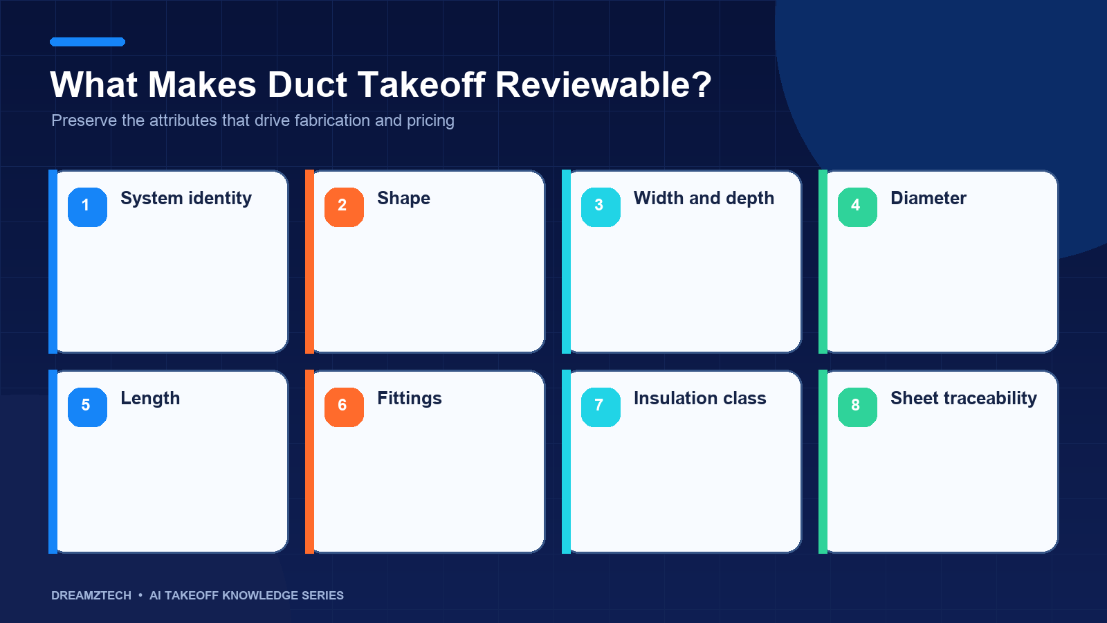
A single total of duct length is not useful for pricing. Preserve size and system changes throughout the path.
Step 6: Measure rectangular ductwork
Trace each rectangular duct segment between size changes and fittings. Record width, height, length and system.
Depending on the estimating method, output may include:
- Linear length by size
- Surface area
- Weight or gauge category
- Fabrication class
- Insulation area
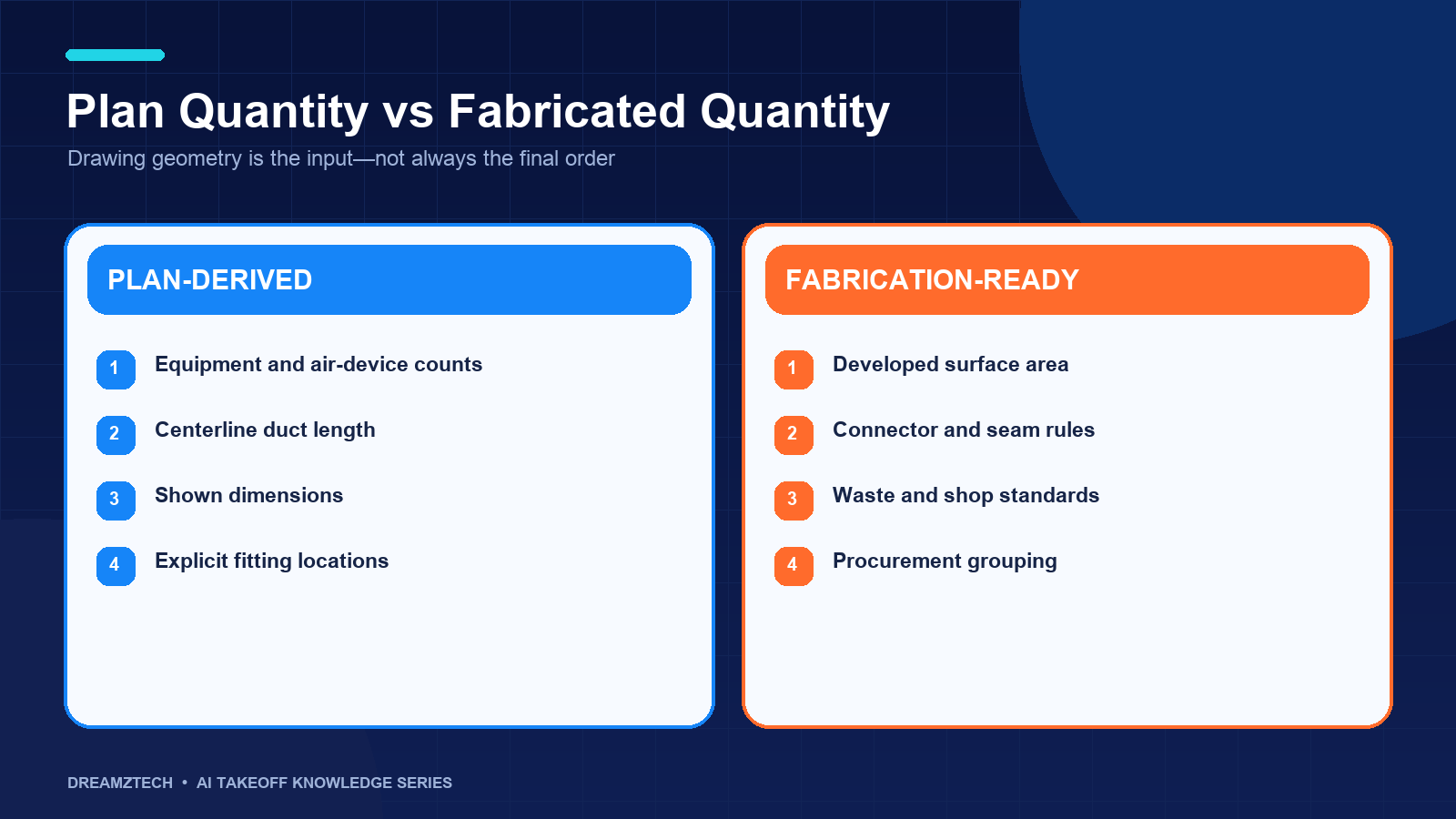
Plan length is not the same as fabricated length. Fittings and transitions may be counted separately or derived under approved rules.
When surface area is calculated, document the formula and whether fitting areas are included.
Step 7: Measure round and spiral duct
Trace round duct by diameter and system. Check:
- Diameter changes
- Branch takeoffs
- Flexible duct connections
- Spiral versus standard round material
- Exposed architectural conditions
- Liner or external insulation
Separate flexible duct from rigid duct because material and labor treatment differ. Confirm any maximum flexible-duct length requirement.
Step 8: Identify fittings and transitions
Fittings create substantial fabrication and labor impact. Common categories include:
- Elbows
- Tees
- Wyes
- Reducers
- Rectangular transitions
- Round transitions
- Square-to-round transitions
- Offsets
- Branch takeoffs
- End caps
Three approaches are common:
- Directly count fittings from drawings
- Derive fittings from traced geometry
- Apply historical factors to duct quantities
Choose one method by system and drawing detail. Do not mix methods without identifying overlap.
AI can help identify geometric changes, but fabrication interpretation still requires estimator review.
Step 9: Review dampers and specialties
Dampers may be shown symbolically, specified by note or required by wall and system conditions.
Review:
- Volume control dampers
- Fire dampers
- Smoke dampers
- Combination fire-smoke dampers
- Backdraft dampers
- Motorized dampers
- Access requirements
Coordinate rated walls and architectural or life-safety plans. A duct plan alone may not show every required damper.
Step 10: Calculate insulation, liner and supports
Insulation and liner depend on duct type, location, system and specifications.
Organize by:
- External insulation
- Internal liner
- Thickness
- Duct surface area
- Exposed or concealed condition
- Indoor or outdoor service
Support quantities may be derived from length using approved spacing, with adjustments for equipment, large duct, trapezes and seismic conditions.
Keep these rules visible so reviewers can change them without altering the base measurement.
Step 11: Review mechanical piping
Where piping is included, separate:
- Chilled water supply and return
- Heating water
- Condenser water
- Refrigerant
- Condensate
- Gas or fuel systems
Measure by system and size, then reconcile equipment connections and vertical scope. Apply the same direct-versus-derived discipline used for plumbing.
Step 12: Coordinate controls and other disciplines
Mechanical equipment may require controls, electrical power, structural support, roof curbs, condensate or plumbing connections.
Create a coordination list with:
- Equipment tag
- Required power
- Controller or sensor
- Disconnect responsibility
- Plumbing connections
- Structural or roofing requirements
- Vendor-furnished components
This process identifies scope gaps that cannot be solved by duct measurement alone.
Step 13: Process revisions and renovation phases
For each addendum or revised issue:
- Register the replaced sheets
- Identify changed equipment and air devices
- Retrace affected duct and piping
- Reconcile schedule changes
- Separate removed and added quantities
- Update fitting and insulation derivations
- Re-approve affected output
Renovation projects require clear separation of demolition, existing-to-remain, relocated and new equipment or ductwork.
HVAC takeoff quality-control checklist
Equipment
- Every tag reconciled with the schedule
- New and existing status confirmed
- Accessories included
- Roof and enlarged plans checked
- Connections coordinated
Air devices
- Types reconciled with the schedule
- Supply, return and exhaust separated
- Linear devices measured correctly
- Repeated rooms checked for exceptions
Ductwork
- Scale verified
- Systems separated
- Shape and size changes retained
- Match lines reconciled
- Flexible and rigid duct separated
- Plan length distinguished from fabrication quantity
Fittings and specialties
- Counting or derivation method documented
- Transitions included
- Damper requirements reviewed
- Access and specialty items considered
Derived quantities
- Surface-area formula documented
- Insulation and liner rules documented
- Support spacing documented
- Waste factors visible
Handoff
- Drawing issue recorded
- Corrections retained
- Reviewer identified
- Direct and derived quantities separated
- Output matches estimating categories
How AI-assisted HVAC takeoff helps
AI can assist with:
- Equipment and air-device recognition
- Initial schedule mapping
- Duct-path measurement
- Size and system organization
- Drawing and revision indexing
- Review prioritization
- Structured quantity output
Estimators remain responsible for:
- Ambiguous tags
- Specifications and pressure classes
- Fitting interpretation
- Fabrication rules
- Insulation and support assumptions
- Renovation scope
- Final approval
The workflow should accelerate repetitive measurement while preserving mechanical expertise.
Accuracy testing for HVAC takeoff
Segment evaluation by quantity type.
| Quantity | Evaluation approach |
|---|---|
| Equipment | Tag detection and schedule reconciliation |
| Air devices | Precision and recall by schedule type |
| Duct length | Measurement error by size and system |
| Fittings | Direct count or derivation audit |
| Surface area | Formula and dimensional validation |
| Revisions | Added, removed and unchanged quantity comparison |
Record estimator correction time and drawing quality. Clean performance on a vector plan should not be generalized to older scanned mechanical sheets.
Common HVAC takeoff mistakes
Combining all duct into one length
Pricing requires size, shape, system and often pressure or insulation context.
Ignoring equipment schedules
Plan symbols do not contain every accessory or equipment characteristic.
Treating plan route as fabricated duct
Fittings, transitions, offsets and fabrication methods change the required quantity.
Missing rated-wall dampers
Damper requirements may depend on architectural and life-safety information.
Mixing demolition and new work
Renovation overlays require explicit phase classification.
Hiding rules in the total
Insulation, supports, fittings and waste should remain traceable.
Mechanical clarification and risk log
HVAC documents frequently leave installation decisions open. Record those conditions in a structured log rather than hiding them inside a total.
Common entries include:
- Duct routes blocked by structure or other trades
- Equipment tags that differ between plan and schedule
- Unclear pressure class or material specification
- Missing curb, support or vibration-isolation responsibility
- Rated-wall penetrations without damper detail
- Existing equipment requiring field verification
- Incomplete controls responsibility
- Conflicts between demolition and new-work drawings
For each item, record the drawing reference, quantity category, temporary assumption, potential bid effect and reviewer. If clarification arrives, update the affected quantity and retain the previous decision.
This log is especially important for renovation work, where accurate plan measurement cannot eliminate uncertainty about concealed conditions. AI can locate and organize drawing evidence, but estimators still decide how the risk is priced, qualified or excluded.
Keeping risk separate from measured quantity improves both bid transparency and later change management.
Suggested HVAC quantity output
Include:
- Item class
- Equipment or device tag
- System
- Shape and size
- Count, length or area
- Unit
- Sheet and revision
- Schedule or detail reference
- Direct or derived status
- Assumptions
- Reviewer and approval status
The output should be ready for estimating without removing the evidence required for review.
Moving HVAC quantities into fabrication and estimating
Mechanical quantities often pass through more than one interpretation. The drawing provides plan geometry. The takeoff organizes equipment, devices, duct and piping. Estimating applies material, fabrication, purchased-equipment, labor and productivity assumptions.
Maintain separate fields for:
- Plan length
- Fitting count or derivation
- Fabricated length where calculated
- Duct surface area
- Insulation or liner area
- Material or pressure class
- Hanger and support rule
- Waste factor
This structure prevents one opaque total from driving several cost categories. It also allows fabrication rules to change without modifying the original traced path.
HVAC takeoff by project type
Commercial office
VAV systems, repeated air devices and ceiling coordination are common. Equipment and terminal schedules should reconcile with each floor.
Warehouse and industrial
Large duct, long runs, high-bay equipment and exposed systems increase the importance of routing, support and fabrication assumptions.
Healthcare
Pressure relationships, specialty exhaust, filtration, equipment redundancy and phased renovations increase classification and specification requirements.
Retail and hospitality
Packaged equipment, tenant variations, kitchen exhaust and architectural constraints require equipment and curb coordination.
Renovation
Existing-to-remain, demolition, relocation and new work may overlap. Field conditions and incomplete as-built information should be treated as explicit risk.
Questions for the final mechanical review
- Does every equipment tag match the current schedule?
- Are all air devices assigned to the correct type and system?
- Are duct shape, size and system retained through transitions?
- Are fittings counted or derived without overlap?
- Are dampers coordinated with rated assemblies?
- Are insulation, liner and supports based on documented rules?
- Are renovation phases and addenda separated?
- Does the output represent plan route, fabricated quantity or estimator-adjusted quantity?
Clear answers make the takeoff suitable for estimating and later bid review.
Frequently asked questions
Field, fabrication and coordination considerations
Mechanical plan geometry must be reviewed against fabrication and coordination realities. Ceiling height, structure, access and other trades can change duct routing, fitting count and installation labor.
Consider:
- Beam and joist locations
- Ceiling congestion
- Required access clearances
- Equipment service zones
- Shaft dimensions
- Rated assemblies
- Roof penetrations and curbs
- Large-duct handling and assembly
- Existing occupied conditions
- Phasing and temporary systems
A straight plan segment may require offsets or transitions during coordination. A duct size may fit graphically but not physically pass through the available structure. Equipment replacement may require disassembly, rigging or temporary service that is not represented by the equipment count.
Record coordination allowances separately from traced geometry. Identify the affected system and area, and preserve the assumption for later review. When a coordinated model or revised drawing becomes available, update the allowance and retain the earlier decision.
Fabrication teams may organize duct by pressure class, gauge, connector system and shop standards that are not fully visible on the plan. These mappings should be explicit in the estimating or fabrication workflow rather than implied by a generic duct category.
AI-assisted takeoff can make size-specific geometry and schedule evidence easier to review. Mechanical expertise remains essential for converting that evidence into fabricated and installed scope.
Final HVAC takeoff package
Package the sheet register, equipment and air-device counts, schedule reconciliation, duct and piping measurements, fitting method, derived areas, clarification log and approval record. The estimator should be able to distinguish drawing quantities, fabrication rules and risk allowances without reopening every sheet.
Keep the package with the bid issue so coordination changes and addenda can be compared with an approved mechanical baseline.
What is included in an HVAC takeoff?
Typical scope includes equipment, air devices, ductwork by size and system, fittings, dampers, insulation, liner, supports and mechanical piping where applicable.
Can HVAC takeoff software measure ductwork from PDFs?
It can measure plan paths after scale calibration and organize them by size and system. Fabricated quantities, fittings, transitions and offsets require defined rules and estimator review.
Can AI reconcile mechanical equipment schedules?
AI-assisted workflows can connect detected tags with schedule entries, but conflicting or missing information should be resolved by an estimator.
Is HVAC takeoff the same as HVAC estimating?
No. Takeoff produces physical quantities. Estimating applies material, fabrication, equipment, labor, productivity, overhead and margin.
Should fittings be counted or derived?
Use the method supported by drawing detail and company standards. Document the method and prevent overlap between direct counts and factors.
What drawings should be used for a software test?
Use a completed project with equipment and air-device schedules, multiple duct sizes, fittings, an enlarged area and a revision or renovation phase if representative.
Evaluate the HVAC workflow on a completed project
Apply the checklist to drawings your estimators already understand. Compare equipment, air devices, duct quantities, fittings, schedule reconciliation and review effort.
DreamzTech can demonstrate equipment and air-device detection, scale-calibrated duct measurement, fitting review, revision handling and structured mechanical output on your plan set. Request an HVAC takeoff software demo to assess the workflow using your own drawings.