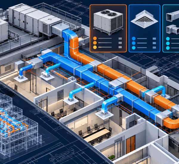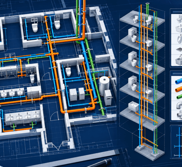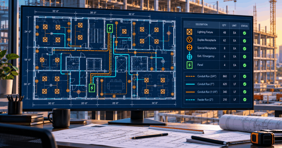
An electrical takeoff should identify the controlling drawing issue, map the project legend, count devices and fixtures by class, reconcile panels and schedules, measure applicable runs from verified scale, document allowances and route every quantity through estimator review before pricing.
The checklist below is designed for electrical contractors evaluating manual, digital or AI-assisted takeoff workflows. It separates directly observed drawing quantities from estimating assumptions so reviewers can understand how every number was produced.
It also gives estimating leaders a consistent basis for comparing manual and AI-assisted results across representative projects, using the same scope rules, quantity definitions and review expectations.
DreamzTech’s electrical takeoff software supports a reviewable workflow for drawing intake, legend mapping, counts, measured runs, corrections and structured quantity handoff.
Electrical takeoff preparation checklist
Before counting, confirm the project documents and the requested scope.
Drawing control
- Confirm bid date and current addendum
- Record the drawing issue and revision
- Compare the uploaded sheets with the drawing index
- Separate superseded sheets
- Identify demolition and new-work plans
- Flag match lines, enlarged plans and typical floors
- Confirm whether architectural backgrounds are current
Electrical sheet inventory
- Cover and general notes
- Symbol legend and abbreviations
- Site electrical plans
- Lighting plans
- Power plans
- Low-voltage plans
- Fire-alarm plans
- Single-line diagrams
- Panel schedules
- Lighting fixture schedules
- Equipment schedules
- Details and specifications
Commercial scope
- Base bid and alternates
- Owner-furnished or contractor-furnished equipment
- Work by others
- Existing-to-remain systems
- Temporary power
- Permits and utility scope
- Testing and commissioning
- Exclusions and qualifications
Takeoff software can organize plan-based quantities, but commercial scope still requires estimator authority.
Step 1: Read the notes, legend and specifications
Do not begin with device counting. Start by understanding the symbol system and project rules.
Review:
- Device legend
- Lighting fixture types
- Mounting designations
- Emergency and normal-power conventions
- Circuiting graphics
- Homerun notation
- Panel naming
- Low-voltage system legends
- Demolition graphics
- Detail references
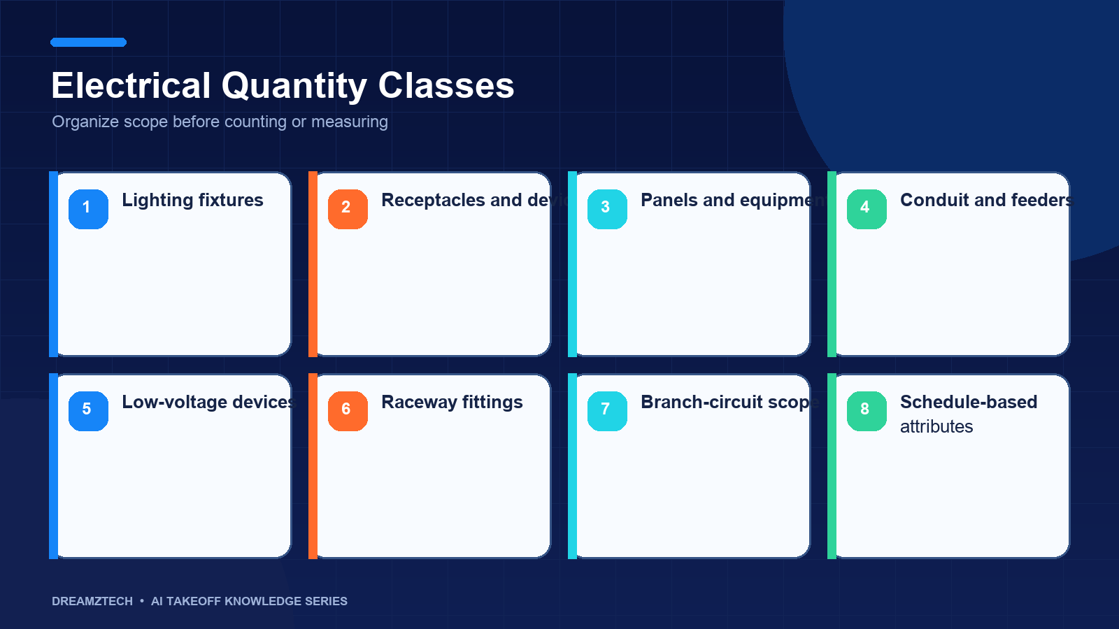
Create a project-specific class map. For each symbol, record the drawing label, takeoff description, intended assembly and any ambiguity requiring review.
Similar-looking symbols may represent materially different scope. A receptacle with a small notation may indicate dedicated, isolated-ground, GFCI, weather-resistant or controlled service. A generic model or symbol library should not remove those distinctions.
Step 2: Establish the counting structure
Organize counts in the same way the estimate will consume them.
A practical structure may include:
Wiring devices
- Standard receptacles
- GFCI receptacles
- Specialty receptacles
- Floor boxes
- Disconnect switches
- Single-pole and multi-way switches
- Dimmers and controls
- Junction and pull boxes
Lighting
- Fixtures by schedule type
- Emergency fixtures
- Exit signs
- Exterior lighting
- Lighting controls and sensors
- Drivers, transformers or control packs where scheduled
Distribution and equipment
- Panelboards
- Switchboards
- Transformers
- Generators
- Automatic transfer switches
- Motor control equipment
- Disconnects
- Equipment connections
Low-voltage and life safety
- Data outlets
- Wireless access points
- Security devices
- Fire-alarm initiating and notification devices
- Access-control devices
- Cameras
- Public-address devices
Keep systems separate even when symbols look similar. Their pathways, equipment and pricing structures differ.
Step 3: Count devices and fixtures by class
Count one class at a time across the relevant sheets. Preserve locations or annotations so every total can be reviewed.
For manual takeoff, use consistent markup colors and completed-sheet indicators. For AI-assisted takeoff, require visible detections rather than totals alone.
Check for:
- Symbols hidden by room tags or dimensions
- Devices at match lines
- Typical rooms repeated across floors
- Enlarged plans duplicating base-plan symbols
- Demolition and new-work overlays
- Symbols located in details rather than floor plans
- Addendum clouds and revised areas
After each class, reconcile the count with room types, typical-unit logic and schedules where applicable.
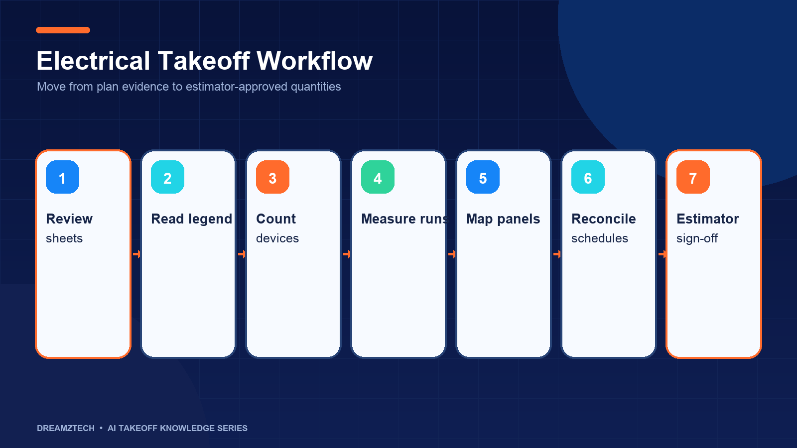
Step 4: Reconcile lighting fixture schedules
Lighting fixtures should be counted by schedule type rather than visual appearance alone.
Verify:
- Type designation
- Normal or emergency operation
- Mounting method
- Voltage
- Controls
- Accessories
- Exterior rating
- Alternate or allowance notes
Compare the plan count with the fixture schedule. Investigate schedule types that appear in the schedule but not on plans, and symbols that lack a schedule definition.
Do not assume the fixture schedule quantity is authoritative unless the documents explicitly provide one. Most schedules define types, while the plans determine quantity.
Step 5: Review panels, feeders and single-line diagrams
Panel and equipment quantities should be reconciled across floor plans, schedules and single-line diagrams.
For each panel or distribution item, record:
- Tag
- Location
- Voltage and phase
- Main rating
- Mounting
- Feeder relationship
- New or existing status
- Source and downstream equipment
Check whether panels shown on the single-line diagram appear on the plan and schedule. Identify spare, future or existing designations that should not be priced as new equipment.
For feeders, confirm conductor and raceway information from the governing schedule or diagram. A graphical connection does not always contain sufficient sizing information.
Step 6: Measure conduit, cable tray and other runs
Before measuring, verify scale against a known dimension. Do not rely exclusively on the title block because PDFs may be resized during export.
Measure and categorize runs by the attributes relevant to pricing, such as:
- System
- Raceway type
- Size
- Conductor category
- Routing zone
- Underground, concealed or exposed condition
- Fire-rated or hazardous-area requirement
Plan-route length is not installed length. The estimator may need to add:
- Vertical rises and drops
- Equipment connections
- Routing around structure
- Waste
- Supports
- Fittings
- Pull points
- Seismic requirements
Keep directly measured footage separate from allowances. That distinction allows reviewers to challenge or reuse assumptions.
Step 7: Evaluate homeruns and circuit routing
Homerun graphics can be ambiguous. They may indicate circuit association without defining the complete physical route.
Review:
- Circuit numbers
- Panel source
- Shared neutral or multiwire conventions
- Home-run start point
- Assumed route to the panel
- Ceiling and pathway constraints
- Typical circuiting notes
If the drawing does not establish routing, label the measured quantity as an estimator assumption. Do not present an inferred route as directly drawn.
Step 8: Include boxes, fittings and supports
Some items are drawn directly. Others are derived from device count or measured length.
Common derived categories include:
- Device boxes
- Covers and plates
- Conduit fittings
- Cable tray fittings
- Supports and hangers
- Grounding accessories
- Firestopping
- Identification
- Testing allowances
Document the rule used. For example, one box per device may be straightforward, but multi-gang conditions and specialty boxes require adjustment.
AI-assisted takeoff can automate the base count while estimator-approved rules produce derived quantities transparently.
Step 9: Review equipment connections
Electrical scope often depends on mechanical, plumbing, kitchen, fire-protection or architectural equipment schedules.
Create an equipment-connection list with:
- Equipment tag
- Source drawing
- Voltage and phase
- Disconnect requirement
- Starter or controller responsibility
- Raceway and conductor allowance
- Control wiring responsibility
- Equipment furnished by
Cross-discipline coordination prevents missed connections that do not appear clearly on the electrical plan.
Step 10: Process revisions and addenda
For each addendum:
- Register replaced sheets
- Preserve the previous issue
- Identify changed regions
- Recount or remeasure affected classes
- Reconcile schedule changes
- Record added and removed quantities
- Re-approve affected output
Avoid rerunning the entire takeoff without understanding which source changed. Revision-aware workflows should focus review while preserving traceability.
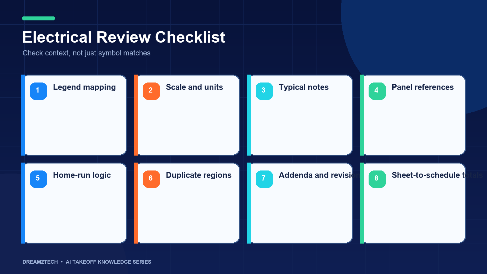
Electrical takeoff review checklist
Device counts
- Every class mapped to the project legend
- Similar symbols reviewed separately
- Match lines checked
- Enlarged plans checked for duplication
- Typical floors validated individually
- Demolition and new work separated
Lighting
- Counts reconciled to fixture types
- Emergency designations confirmed
- Controls and sensors included
- Exterior and specialty fixtures checked
- Schedule discrepancies logged
Distribution
- Panels reconciled across plan, schedule and single-line
- New and existing equipment separated
- Transformer and disconnect scope confirmed
- Feeders linked to source information
Measured runs
- Scale verified per sheet
- Paths visible for review
- Runs categorized by system and size
- Vertical and routing allowances stated
- Waste and fittings separated
Review and handoff
- Corrections recorded
- Drawing revision attached
- Reviewer identified
- Assumptions included
- Approved quantities mapped to estimating categories
How AI-assisted electrical takeoff changes the workflow
AI can accelerate repeated symbol location and initial plan measurement. The estimator’s work shifts toward:
- Confirming the legend map
- Reviewing low-confidence items
- Searching for missed symbols
- Reconciling panels and schedules
- Confirming scale and routing
- Approving derived rules
- Resolving scope and specifications
The objective is not to remove review. It is to reduce the time spent placing the same markup on dozens of sheets while retaining estimator control.
Accuracy metrics for electrical quantities
Evaluate each important class independently.
| Metric | Electrical example |
|---|---|
| Precision | Detected receptacles that were actually receptacles |
| Recall | True receptacles found by the workflow |
| Misclassification rate | Devices assigned to the wrong legend class |
| Measurement error | Difference in reviewed conduit or tray length |
| Correction time | Estimator time to reach approved quantity |
Also record the design firm, drawing quality and revision. Performance on one legend should not be generalized across every project.
Common electrical takeoff mistakes
Counting before mapping the legend
This produces fast totals with unreliable classes.
Treating repeated floors as identical
Unit layouts may repeat while common areas, risers and equipment change.
Measuring the shortest graphical route
The installed route may respond to structure, access and pathway requirements.
Ignoring schedules and single-line diagrams
Plan views do not contain every equipment or feeder attribute.
Combining low-voltage systems
Data, fire alarm, security and access control should retain separate legends and assemblies.
Hiding allowances inside measured footage
Reviewers should see what came from the drawing and what came from an estimating rule.
Electrical bid review questions
Before the takeoff is released for pricing, the lead estimator should ask:
- Does every counted class match the current legend?
- Were lighting fixtures reconciled with the latest schedule?
- Do panels and distribution equipment agree across plans, schedules and single-line diagrams?
- Were low-voltage and life-safety systems kept separate?
- Was scale verified on every measured sheet?
- Are homerun and routing assumptions visible?
- Were typical floors checked for exceptions?
- Are demolition and new-work quantities isolated?
- Are boxes, fittings and supports counted or derived consistently?
- Can each major quantity be traced to a drawing location or estimator rule?
This review should also identify open questions that affect price but cannot be resolved from the drawings. Carry those questions into bid qualifications rather than embedding optimistic assumptions in the quantity total.
For negotiated or design-assist work, preserve unresolved items as a separate decision log. The same log can be revisited when revised drawings arrive, reducing the risk that an early assumption becomes permanent scope without review.
Suggested electrical takeoff output
At minimum, the quantity schedule should include:
- Item class
- Description
- Count or measurement
- Unit
- Sheet
- Revision
- System
- Panel or schedule reference where applicable
- Direct or derived status
- Estimator note
- Approval status
This structure supports pricing while keeping the derivation available for bid review.
Moving electrical quantities into estimating
The takeoff handoff should preserve enough structure for the estimator to apply labor and material assemblies without reinterpreting the drawings.
A useful mapping process includes:
- Keep the original project symbol class.
- Map it to the company’s takeoff description.
- Associate the approved assembly or cost code.
- Preserve the count or measured quantity and unit.
- Attach drawing and revision references.
- Carry direct-versus-derived status into the estimate.
For example, one receptacle symbol may map to a device, box, plate, connectors, conductors and raceway assumptions. The takeoff should not hide that assembly logic inside the detected count. Separating the observed device from the pricing assembly allows the estimator to update material and labor standards without changing the drawing evidence.
Electrical takeoff by project type
Commercial office
Expect repeated device and lighting classes, detailed fixture schedules, floor-box coordination and frequent addenda. Typical floors can improve speed but require exception checks.
Multifamily
Unit repetition, common areas, meter and distribution scope and floor-by-floor variations are central. Confirm that unit multipliers do not duplicate corridor or service quantities.
Warehouse and industrial
High-bay lighting, long feeder or tray routes, equipment connections and specialty power often carry more value than dense device counts. Routing assumptions should be documented carefully.
Healthcare and laboratory
Normal, emergency and critical systems, specialty devices and equipment coordination increase class complexity. Generic symbol grouping is particularly risky.
Renovation
Demolition, relocation, existing-to-remain and new work must be separated. Revision and field-condition risk should remain visible to the estimator.
The same software should not be assumed to perform equally across these project types. Use representative projects when evaluating coverage and correction effort.
Frequently asked questions
Field and constructability considerations
Drawing takeoff provides a controlled measurement basis, but installation conditions can materially change electrical quantities and labor. Estimators should review constructability before treating plan routes as final.
Consider:
- Ceiling type and access
- Structural obstructions
- Exposed versus concealed raceway
- Underground routing and trenching
- Equipment working clearances
- Fire-rated penetrations
- Hazardous or wet locations
- Seismic supports
- Existing occupied conditions
- Phasing and shutdown requirements
A short route on the plan may require a longer installed path around beams, mechanical services or restricted areas. A device count may require different boxes or fittings because of wall construction. Equipment shown diagrammatically may need local disconnects, starters or coordination that is defined elsewhere.
Keep constructability adjustments as estimator-reviewed allowances. Link them to the affected area or system and avoid changing the direct drawing quantity. This allows later drawings or field information to update the allowance without obscuring the original takeoff.
For design-assist projects, use the quantity history to show how scope changes between issues. Added devices, rerouted pathways and equipment changes can then be separated from baseline estimating assumptions.
AI-assisted measurement can make the plan evidence faster to assemble, but it does not replace the field knowledge required to turn that evidence into an installable electrical scope.
Final electrical takeoff package
Before pricing begins, package the sheet register, legend map, approved device counts, measured-run paths, schedule reconciliation, allowances, clarification log and correction history together. This reduces repeated questions and gives the pricing estimator a single controlled source.
Archive the package with the final bid revision so future addenda, negotiations and post-bid questions can be compared against the same approved baseline.
What is included in an electrical takeoff?
Scope varies, but common categories include devices, fixtures, panels, equipment, feeders, conduit, cable tray, boxes, fittings, supports and equipment connections. Pricing and labor belong to estimating.
Can AI count electrical symbols from PDF plans?
It can assist with mapped symbol classes when drawing quality and legend coverage are suitable. Estimators should review false detections, missed items and class assignments.
Can electrical takeoff software measure conduit?
It can measure plan routes after scale calibration. Vertical drops, routing constraints, waste and installed-length allowances still require documented estimator rules.
Is electrical takeoff the same as electrical estimating?
No. Takeoff produces quantities. Estimating applies material prices, labor units, productivity, overhead, margin and commercial strategy.
Why reconcile panel and fixture schedules?
Schedules contain type and equipment information that plan symbols may not show. Reconciliation also exposes missing or conflicting scope.
What should we use to test electrical takeoff software?
Use a completed project with a representative legend, lighting and power sheets, schedules, measured runs and at least one revision if revisions are common.
Evaluate the checklist on your drawings
The checklist becomes valuable when applied to a project your team already understands. Use it to compare manual and AI-assisted workflows class by class, record estimator corrections and measure time to approved output.
DreamzTech can demonstrate legend mapping, device and fixture detection, measured runs, estimator review and structured quantity handoff using your electrical plan set. Request an electrical takeoff software demo to evaluate the workflow against your own reference takeoff.